 We have used phosphor bronze wire pickups acting on the
outer edges of the flanges at the tops of
the wheels. They act on the outer wheelsets only, as there is limited space to fit pickups to the
centre wheels.
We have used phosphor bronze wire pickups acting on the
outer edges of the flanges at the tops of
the wheels. They act on the outer wheelsets only, as there is limited space to fit pickups to the
centre wheels.If you are using the 'American' system of pickup, with the wheels on one side of each bogie 'live' (i.e. with their wheelrims in electrical contact with the axles) then there is no need to provide separate wire pickups; the electrical connection can be made simply to the securing screw at the top of the bolster (unless you are building the Class 55 model, when you might wish to run a separate wire to the bolster to avoid having a wire visible in the cab area).
If, however, you are using fully insulated wheelsets or, whilst using the 'American' system, still wish to add pickups to the 'insulated' side of the bogie, we offer some guidelines below.
We suggest that pickups are mounted in some way on the drive train moulding as there is very little movement between that and the wheelsets. The pickups will not then interfere with the suspension. Various arrangements are possible and you may already have your own preferences. Bear in mind the following:
If you fix any components to the sides of the drive unit moulding, make sure that they do not interfere with the free movement of the drive unit within the bolster and subframe.
If you run wires between the two articulated parts of the drive train, ensure that they do not restrict the articulated movement.
Connecting wires should be sufficiently flexible, or routed in such a way, that they transmit no forces arising from differential movements between the drive unit and the bolster or loco chassis. If this condition is not met, there could be mechanical 'short circuiting' of the suspension, with wobbles and shocks being transmitted directly from the track to the loco body.
Connecting wires should be routed clear of the rotating drive shafts and exposed worms.
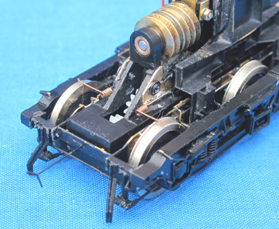
We have used phosphor bronze wire pickups acting on the
outer edges of the flanges at the tops of
the wheels. They act on the outer wheelsets only, as there is limited space to fit pickups to the
centre wheels.
A procedure for fitting this type of pickup is described below. A similar approach can be used for both four- and six-wheel drive units.
 To anchor the pickups to the drive unit, we have provided some brass plates, parts 11 on Fret F008, to
be used in conjunction with the pickup templates which are printed on one of the paper inserts to the
kit packaging. Parts 11 form part of the margins of the fret. Their finished shapes are shown
on the templates. The templates assist in soldering up the pickup assemblies remote from the drive unit,
allowing better control of assembly than attempting it in-situ.
To anchor the pickups to the drive unit, we have provided some brass plates, parts 11 on Fret F008, to
be used in conjunction with the pickup templates which are printed on one of the paper inserts to the
kit packaging. Parts 11 form part of the margins of the fret. Their finished shapes are shown
on the templates. The templates assist in soldering up the pickup assemblies remote from the drive unit,
allowing better control of assembly than attempting it in-situ.
Cut parts 11 from the fret margins and finish them to the shapes shown on the templates.
Stick the templates to a flat, heatproof surface with double sided tape. Apply small pieces of double sided tape to the face of the templates to hold the brass plates.
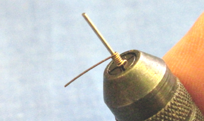 Form the wire pickups.
We use 0.011" phosphor bronze, with coils formed around the shank of a 0.7mm drill held in a pin chuck. Start with a right angled bend in the wire, 10mm or so from the end, and insert the end into one of the slots of the chuck's collet. Keeping the free end of the wire under light tension between the fingers, rotate the chuck in the desired direction, five or six complete revolutions, to form the coils. Stop rotating at the angle which leaves the free end of the wire exiting the coil on the opposite side to the captive end at the base of the coil…
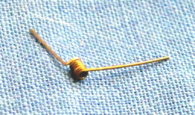 …then trim the free end of the wire to about 10mm and slide the coil off the end of the drill.
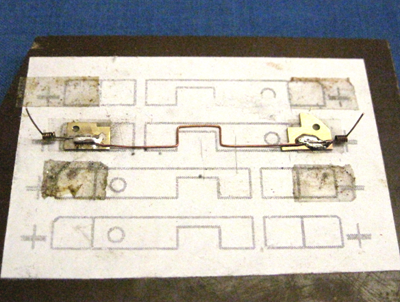
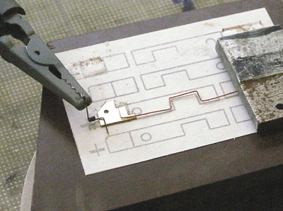 Stick one pair of brass plates to the templates in the indicated positions (if you are fitting out
a four-wheel drive unit you will need to use different positions for the plates at the inboard
end of the unit).
Stick one pair of brass plates to the templates in the indicated positions (if you are fitting out
a four-wheel drive unit you will need to use different positions for the plates at the inboard
end of the unit).
Solder a connecting wire between the two plates. This should be bent to a shape similar to that shown in the photos, to allow articulation of the drive unit between the two plates. Use resin-cored solder for all these electrical connections. Keep the areas around the holes in the plates clear.
We used laquered copper wire from an old winding for the connecting wires: flexible, and insulated.
Support the pickups at the orientation and locations indicated by the crosses on the template (upper crossbars for 3'9" wheels, lower for 3'7") and solder them in place.
 Remove the pickups from the template, seeking to avoid any distortion of the connecting wire. Repeat for
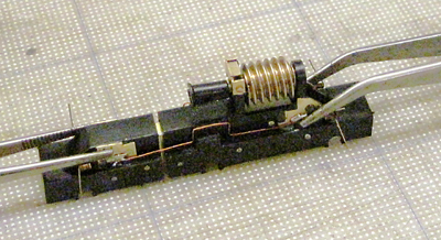
the remaining three sets of pickups. When complete, glue the pairs of plates to the sides of their drive units.
Remove the pickups from the template, seeking to avoid any distortion of the connecting wire. Repeat for
the remaining three sets of pickups. When complete, glue the pairs of plates to the sides of their drive units.
We use quick set epoxy, thoroughly degrease the mating surfaces on the drive unit and the brass plates, and score the surface of the drive unit to provide a key for the adhesive.
 Once the glue has set, decide at which end of the drive unit you wish to connect the pickup wires. This
will reflect the locations at which the pickup wires are to pass through the chassis block (outboard or
inboard of the bogie pivot). Holes are provided in the bolster tops to assist in securing the wires clear
of rotating components; use of these would imply that the wires would be secured to the drive unit to the
opposite side of the pivot to that at which they pass through the chassis block.
Once the glue has set, decide at which end of the drive unit you wish to connect the pickup wires. This
will reflect the locations at which the pickup wires are to pass through the chassis block (outboard or
inboard of the bogie pivot). Holes are provided in the bolster tops to assist in securing the wires clear
of rotating components; use of these would imply that the wires would be secured to the drive unit to the
opposite side of the pivot to that at which they pass through the chassis block.
Having decided on the location of the pickup wire connections, clear away any glue from around the holes in the pickup plates at that end. Drill through the holes into the drive train moulding with a 0.9mm drill, deeply enough to take the cross-headed screws which originally retained the pickup strips fitted by Bachmann. You shouldn't be drilling through the moulding where there is a gear wheel within, but do check. Fit the screws into the holes to cut new threads.
Clean any swarf and dust from the drive unit.
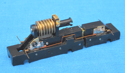
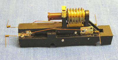 That concludes the description of the procedure for fitting pickups to the six-wheel drive units.
A similar approach, illustrated here, can be used for a four-wheel drive bogie. There is some relative
movement to be accommodated between the inner pickups and their wheelset.
That concludes the description of the procedure for fitting pickups to the six-wheel drive units.
A similar approach, illustrated here, can be used for a four-wheel drive bogie. There is some relative
movement to be accommodated between the inner pickups and their wheelset.