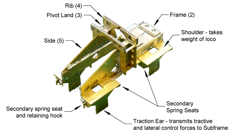
This section describes the assembly of the Bogie Bolsters.
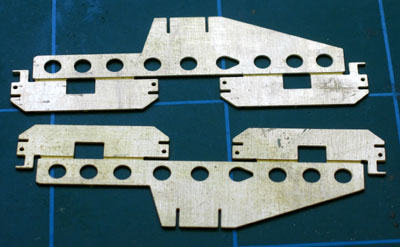
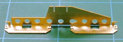
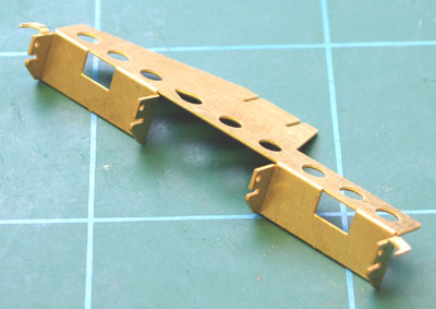
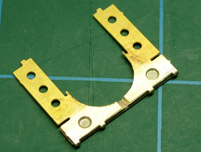
 Remove a Bolster Frame etch (2) from the fret.
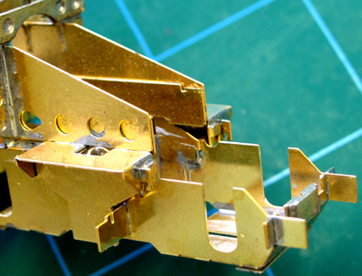
Using a round needle file, make a gap in the copper cladding of each of the PCB strips visible in the slots between the two halves of the Frame.
Check that the slots indicated in the diagram below are clear to pass the material thickness.
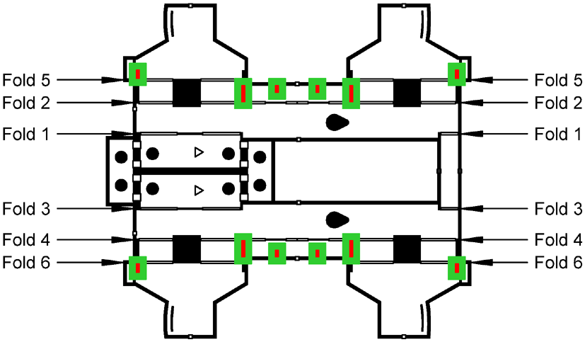
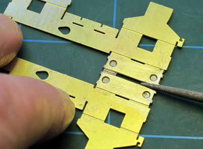
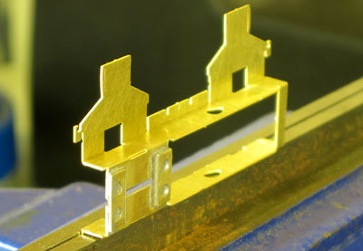
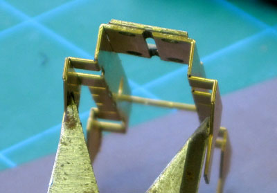
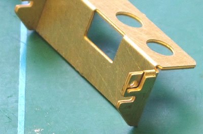
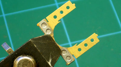
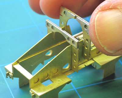
 Make the innermost fold, Fold 1, which is in two parts along one side of the Bolster Frame.
 On the same side, make the next fold out, Fold 2 (note that this fold-line is on the opposite face of the etch to the first)
 Repeat the above folds, Folds 3 and 4, in the same order, on the opposite side of the Frame…
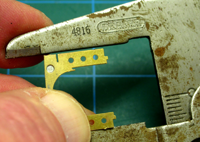
 …you might need some creative thinking to work out how to drive the folds over. A flat wooden lolly stick
fits the central space very nicely.
…you might need some creative thinking to work out how to drive the folds over. A flat wooden lolly stick
fits the central space very nicely.
 Check that the folds made so far are at 90°, and adjust as necessary.
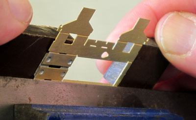
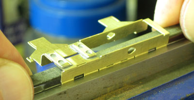
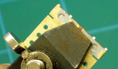
 Fold down the two traction ears, Folds 5 and 6, on each side of the Frame.
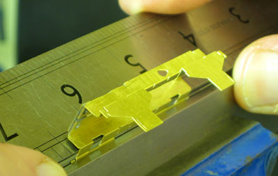
 Check that the ears are vertical, parallel (you can use your second-best vernier for this)…
 …and that the
Frame sits square on the ears on a flat plate.
…and that the
Frame sits square on the ears on a flat plate.
 Match up the Frame with its Subframe (as indicated by the presence or absence of the half-etched triangular marks
on each) and check that the width over the Subframe's lateral control ears is the same or greater than the
width between the Frame's traction ears (you will file them down to the correct size later). If it is not, adjust the folding accordingly as far as you can,
keeping the ears and the sides of the frame vertical and parallel, and the frame folds at 90°.
Match up the Frame with its Subframe (as indicated by the presence or absence of the half-etched triangular marks
on each) and check that the width over the Subframe's lateral control ears is the same or greater than the
width between the Frame's traction ears (you will file them down to the correct size later). If it is not, adjust the folding accordingly as far as you can,
keeping the ears and the sides of the frame vertical and parallel, and the frame folds at 90°.
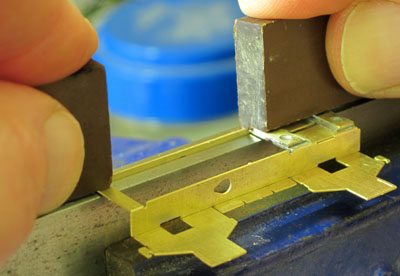
 Reinforce Folds 1 and 3 with solder.
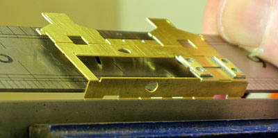
 Check again that the slots along the sides of the Frame are still clear to take the material thickness, now
that the folds have been made.
Check again that the slots along the sides of the Frame are still clear to take the material thickness, now
that the folds have been made.
 Remove the Bolster Sides (5) from the fret. There is one of each hand for each bogie.
Check that the two slots in the top, and the four small slots in the lower part, of each Bolster Side are clear to take the material thickness.
 Make the long 90° fold in the Sides. Note that the small lugs, whose fold-lines are on the opposite side
of the etch, are also folded over.
Make the long 90° fold in the Sides. Note that the small lugs, whose fold-lines are on the opposite side
of the etch, are also folded over.
 Fold down the four secondary suspension seats on each Side.
 Complete the 180° folds of the small lugs to bring them round flush onto the outer faces of each outside
secondary suspension seat.
Complete the 180° folds of the small lugs to bring them round flush onto the outer faces of each outside
secondary suspension seat.
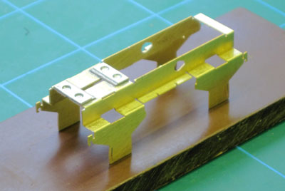
 Fit the Sides to the Frame - match up the 'Raindrop' shaped holes to indicate that you have the Sides correctly
handed on the Frame. Slide them vertically into place…
Fit the Sides to the Frame - match up the 'Raindrop' shaped holes to indicate that you have the Sides correctly
handed on the Frame. Slide them vertically into place…
 …and engage the spring seats into their tabs and slots at the top of the ears.
 Remove the Bolster Ribs (4) from the fret. There are two Ribs for each bogie.
Check that the slots near the top of each side are clear to take the material thickness.
File away the excess PCB material from the top of the arch of each Rib.
 Using a round needle file, make a gap in the copper cladding of the PCB visible in the slot at the top of the
arch of each Rib.
Using a round needle file, make a gap in the copper cladding of the PCB visible in the slot at the top of the
arch of each Rib.
 File away the four folding tabs along the top of each Rib. Check that there are no
metal fragments or solder bridges across the edges of the PCB strips, using files, a sharp knife or
glass-fibre brush
if necessary. Use a test meter to check that the two halves of the
Rib, and the folded over part, are electrically isolated from each other.
File away the four folding tabs along the top of each Rib. Check that there are no
metal fragments or solder bridges across the edges of the PCB strips, using files, a sharp knife or
glass-fibre brush
if necessary. Use a test meter to check that the two halves of the
Rib, and the folded over part, are electrically isolated from each other.
 Check that the two legs of the ribs are still parallel, adjusting as necessary.
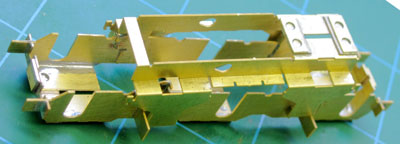
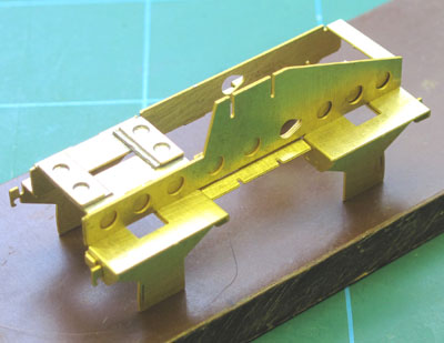
 Fit the Ribs into place over the Frame and Sides, engaging in the various tabs and slots. Note that the
insulating wrapover parts of the Ribs face outwards, away from each other.
Fit the Ribs into place over the Frame and Sides, engaging in the various tabs and slots. Note that the
insulating wrapover parts of the Ribs face outwards, away from each other.
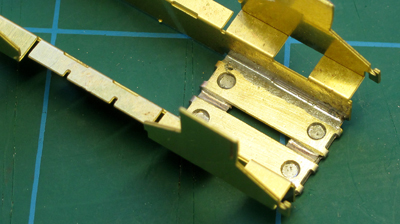
With the whole assembly square and sitting on a flat surface, apply flux and solder all the components together. For the moment, do not solder the upper parts of the Ribs.
Work on one corner, or less, of the assembly at a time. Apply flux to all access points, with a good wetting agent, and apply a goodly amount of solder, on the iron, to points where components meet. Allow the iron to linger, and you will see the solder flash away into the joints between the nearby parts of the assembly.
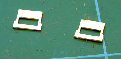 Remove the Pivot Lands (3) from the fret. There are two of these for each bogie.
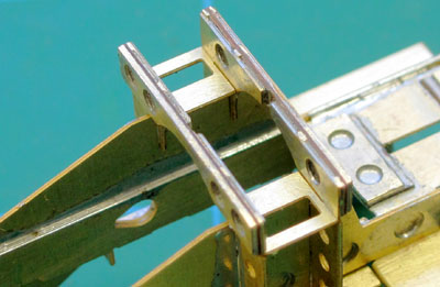 Fit the Pivot Lands into the slots at the tops of the Ribs.
Solder around the Pivot Lands and the tops of the Ribs: apply the solder to the undersides of the lands, so as to keep the channel across the top of the bolster, formed by the lands and the ribs, clear of any fillets of solder.
 File away the four folding tabs from each of the PCB wrapovers on the flat deck of the
Bolster Frame.
File away the four folding tabs from each of the PCB wrapovers on the flat deck of the
Bolster Frame.
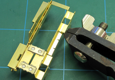
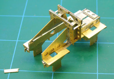
Remove the jigging cross-member from the other end of the Bolster Frame.
Using a test meter, check that the two halves of the Bolster assembly, and the wrapover segments, are electrically isolated each from the others. If not, check that there are no metal fragments or solder bridges across the edges of the PCB strips, using files, a sharp knife or glass-fibre brush as necessary. Checking for shorts between the two halves of the bolster and the wrapovers can help to localize any problem.
 Pair up the bolster with its subframe, as designated by the presence or absence
of the etched triangular marks on the Bolster Frame and the Subframe Mainframe. Orientate the Bolster and
Subframe correctly (the bogie wheelbase is asymmetric) - the outer end of the Subframe has the 'two-dot' axle
markings, while the outer end of the
Bolster is the open end, with the sides angled up towards the pivot.
Pair up the bolster with its subframe, as designated by the presence or absence
of the etched triangular marks on the Bolster Frame and the Subframe Mainframe. Orientate the Bolster and
Subframe correctly (the bogie wheelbase is asymmetric) - the outer end of the Subframe has the 'two-dot' axle
markings, while the outer end of the
Bolster is the open end, with the sides angled up towards the pivot.
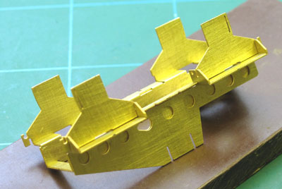
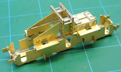
Check the bolster for dimensions and squareness:
 when the bolster is pushed down on to the subframe as far as it will go, as shown here, it should sit on the four
secondary suspension seats of the subframe, with the lower edges of its eight secondary suspension seats
accommodated in the four indentations along the top edge of each side of the subframe.
when the bolster is pushed down on to the subframe as far as it will go, as shown here, it should sit on the four
secondary suspension seats of the subframe, with the lower edges of its eight secondary suspension seats
accommodated in the four indentations along the top edge of each side of the subframe.A tight fit can be addressed in the first instance by light filing on the circular edges of the traction ears or lateral control ears: they have been drawn to be slightly over-size with half-etched guides provided to help preserve the correct shape. Other adjustments may be made by gentle tweaking of either the bolster assembly or the longitudinal control ears. If you do need to tweak the bolster, try to end up with the faces of the traction ears vertical.