General Notes
A Few Words …
These advices, taken, several moons since, from John Lythgoe's instructions for his
Formil Model Engineering Dyna-drive kits, have proved to be useful and enduring tenets:
- "Proceed with patience and due care at ALL stages and a
free-running locomotive should result."
- "Allow sufficient time to spread the conversion over a
number of modelling sessions."
- "Work in good light conditions. Use an anglepoise-type lamp if
possible. A self-supported magnifier is a useful aid."
Safety
Our kits are intended to be assembled by adult modellers, with some workshop experience and awareness,
who are able to
exercise due care and attention when handling the materials and carrying out the various operations
involved. Many of the metal
components have sharp edges. Chemical products used in assembly can be injurious through contact with
skin or eyes, ingestion or inhalation. Some processes involve high temperatures. The user should be
aware of and follow
the manufacturers' or suppliers' safety data and instructions for all tools, materials and products.
The Instructions
The instructions are available on line in both HTML and pdf formats. The HTML versions have
one page for each major section, whilst the pdf versions have a single file for each kit.
Structure
We've divided up the instructions into "narrative" paragraphs, like this one,
which indicate what is being accomplished by a particular stage,
"instruction" paragraphs, like this one, with the tick-box;
"box-ticking" not our favourite activity perhaps but nonetheless can be
useful, on a printed copy, for recording progress and making sure nothing is forgotten,
and "advisory" paragraphs, like this one, which pass on techniques that we
found useful but aren't necessarily the best way, or the only way, of achieving a result.
Printing
We have introduced a "Check List" for some of the kits, which contains the texts of all the instruction
paragraphs for the kit. This is a great deal more compact for printing than the full instructions, and
perhaps more suitable for the workshop. The Check Lists are available only from the on-line copy of
the instructions, from this Index Page.
We intend the Full Instructions to be viewed 'on-screen'. If you did need any of the diagrams or pictures in
the workshop, you could download and print them individually (from the HTML instruction pages) to complement the Check List.
The pdf files can be printed in full or in parts to your own printer using your pdf viewer. Full printouts
in booklet form can also be produced using third party services. For more information visit our
Printing the pdf Files page.
If you wish to print out sections of the HTML instructions, they are formatted in standard
HTML/CSS but, even so, the print function in some browsers does a better
job of rendering them than others. We find
that 'Print' function of the Google Chrome browser produces a good printed result: it also
gives the option of 'Save as PDF', which is a convenient way of creating a single portable file,
including all the illustrations, which you
can view or print on any device.
If your printer can produce half-size A5 prints (two per A4 sheet) or, better still,
double-sided A5 booklet printing, using those options can save a great deal of paper.
The Etches
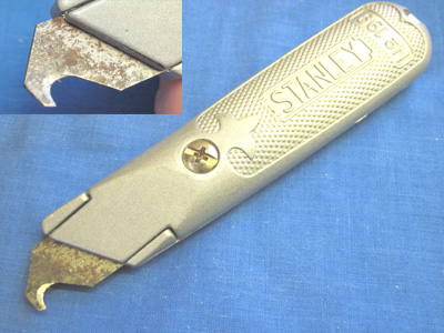 Components are attached to the fret by small half-etched tags. These can be cut through
using a heavy craft knife with an old, stubby, blade (avoid the thin, pointed, 'scalpel'
types, as they will break), against a hard surface. We keep a rigid Stanley
knife expressly for this purpose, with an old carpet trimming blade ground to shape as shown.
Components are attached to the fret by small half-etched tags. These can be cut through
using a heavy craft knife with an old, stubby, blade (avoid the thin, pointed, 'scalpel'
types, as they will break), against a hard surface. We keep a rigid Stanley
knife expressly for this purpose, with an old carpet trimming blade ground to shape as shown.
Any remnants of the tag may be cleaned up using a flat file. We have tried
to avoid putting tags on mating faces, but there are some instances where they need to be
removed thoroughly.
Slots
 Some of the parts of our kits are designed to fit, perpendicularly, either into or through slots in
other parts. The slots
are intended to provide a loose sliding fit for the other part. Because of variations in the degree of etching (q.v., below),
it is possible that the fit will be looser or tighter than ideal.
Some of the parts of our kits are designed to fit, perpendicularly, either into or through slots in
other parts. The slots
are intended to provide a loose sliding fit for the other part. Because of variations in the degree of etching (q.v., below),
it is possible that the fit will be looser or tighter than ideal.
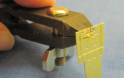
Check the width of each slot with a piece of scrap etch
before assembly, preferably before folding the slotted part. If the scrap will not pass through,
hold it in pliers or a hand vice, as shown (though make sure the part is well supported), and work it
through the slot
until the loose sliding fit is achieved. In tight spots, it is possible to use a small drill held in a
pin chuck as a file.
Degree of Etching
The etch is created for us by a third party industrial manufacturer using a process of chemical erosion.
The 'Degree of Etching', i.e. how long the metal sheet is left in the chemical bath, is a variable which
is set by the skill and judgement of the operator as each batch of sheets is produced. That
dictates that the sizes of the etched parts on different sheets can vary, within a certain tolerance,
around the nominally designed values. The variation is more significant with the relatively thick materials,
that we use in the main structural parts of our kits, than it is with the thinner materials typically
used for detail parts.
The ideal degree of etching is indicated by the slots (see above), as manufactured,
being just slightly on the tight side of the easy sliding fit required. The range of degree of etching
which we deem
to be acceptable is from a 'lighter' etch, in which the scrap material has to be pushed through the slot
quite firmly to achieve the clearance, to a 'heavier' etch, where the fit is a little loose. We have test
built our kits from etches across this range to confirm that they may be assembled successfully.
Cusps
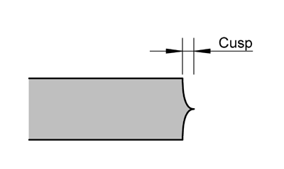 The chemical erosion process works equally from each side of the metal,
resulting in the edges of the etch having shaped 'cusps' as in the diagram here. On edges which will
be visible on the finished model, it is good practice to file the edges of the metal flat. Many of the
edges on our kits are hidden from view.
The chemical erosion process works equally from each side of the metal,
resulting in the edges of the etch having shaped 'cusps' as in the diagram here. On edges which will
be visible on the finished model, it is good practice to file the edges of the metal flat. Many of the
edges on our kits are hidden from view.
Where edges form joints with other components, on a 'lighter'
etch the edges may need to be filed to a flat surface to achieve a fit, whereas with a 'heavier' etch
one might leave more of the cusps in place. In places which can't be reached
by a file, e.g. in acute corners of the etch, the cusp may be pared away with a sharp knife.
Folds
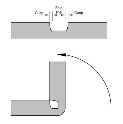 Folds are indicated on the etches by half-etched lines. Unless stated otherwise, all folds are made
at 90° with the half-etched line on the inside of the fold. Most folds may be made by holding the larger
part of
the workpiece in the fingers or, for smaller items, a hand vice or similar clamp, and then driving the
fold from the smaller part either by using smooth-jawed
pliers or by turning it over against a smooth, flat, hard block of material such as hardwood, metal or tufnol.
For longer folds the workpiece may be clamped between two flat, straight edged pieces of similar material.
Special folding tools or bending bars are not necessary,
though of course you may find them useful if you have them.
Folds are indicated on the etches by half-etched lines. Unless stated otherwise, all folds are made
at 90° with the half-etched line on the inside of the fold. Most folds may be made by holding the larger
part of
the workpiece in the fingers or, for smaller items, a hand vice or similar clamp, and then driving the
fold from the smaller part either by using smooth-jawed
pliers or by turning it over against a smooth, flat, hard block of material such as hardwood, metal or tufnol.
For longer folds the workpiece may be clamped between two flat, straight edged pieces of similar material.
Special folding tools or bending bars are not necessary,
though of course you may find them useful if you have them.
Whichever way you make a fold, try not to force its location or direction, but let the brass bend at
its weakest point as determined by the centre of the etched fold line. This should result in a correctly
positioned and symmetric fold as shown in the diagram.
The act of making the fold will work-harden the metal along the line of the fold and may even,
especially with a lighter etch, cause it to yield on the outer corner of the fold. Try, therefore, not to
work a fold unnecessarily once made, as it will become increasingly brittle and prone to breakage. In
general, folds are reinforced with a fillet of solder but this is explicitly dealt with in the instructions
for each component.
Soldering
We use Carrs 145° wire solder with either Carrs Green Label liquid flux or La-Co paste flux,
except where stated otherwise. You will develop a technique that suits yourself and your iron, but the following
notes might help as a starting point.
Flux can be applied to the workpiece using a brush, a pointed cocktail stick or (for paste flux)
a syringe.
With liquid flux, reducing the surface tension of the flux, for example by adding a drop of washing up
liquid or ox-gall, may help it wet the surface. The soldering iron bit is wiped on a damp sponge before each use.
A small amount of solder
can be picked up on the bit (it might need a little flux to help it) and the bit applied to the workpiece, holding it there until the
solder 'flashes' off the bit into the joint; we are using relatively thick material so can afford to linger with the
iron and get plenty of heat to the job. Alternatively a small length of solder wire can be cut off, placed next to
the joint and the iron brought to it. The length can be anything down to the smallest sliver (and even that cut into
smaller sections), giving precise control of the amount of solder applied.
Flux residues should be neutralized and/or cleaned off after each working session. Green Label
flux may be rinsed away with water; a little added citric acid will neutralize it. Liquid or paste fluxes
can be washed away either
with a proprietary flux cleaner or a 50/50 mix of methylated spirits and water.
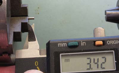
Spring Winding
This section describes a method for producing coil springs, for cosmetic detailing, from wire.
The example shown uses 0.6mm brass wire formed around the shank of a 1.4mm drill, other materials, e.g.
steel or copper, can be used. Such springs will also work functionally, though note that steel of
the correct scale diameter tends to be too stiff.
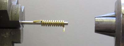
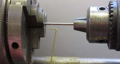 The drill, forming the armature around which the spring is to be wound, is clamped firmly into the lathe chuck with its shank protruding.
The free end of the shank is supported by the chuck in the tailstock, lightly clamped.
The drill, forming the armature around which the spring is to be wound, is clamped firmly into the lathe chuck with its shank protruding.
The free end of the shank is supported by the chuck in the tailstock, lightly clamped.
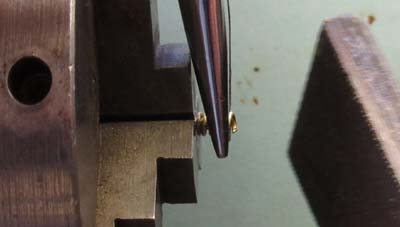
Start with a bend at the end of the wire to form an anchor. Catch it either between the jaws of the chuck
(if they are far enough apart), or (for smaller wire and armature diameters) within the flutes of the drill.
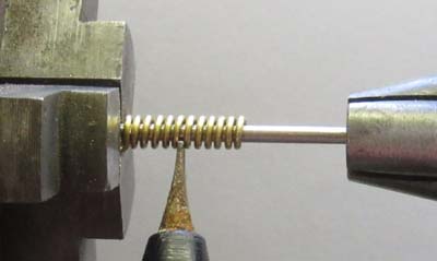
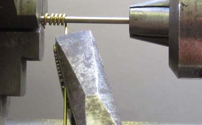 Using a pair of pliers to apply tension, rotate the lathe chuck by hand to wind the wire around the armature. Pay heed
to the direction of winding - a surprising number of diesel bogies were fitted with left-hand wound coil springs (sometimes
with a duplex right-hand wound coil within).
Using a pair of pliers to apply tension, rotate the lathe chuck by hand to wind the wire around the armature. Pay heed
to the direction of winding - a surprising number of diesel bogies were fitted with left-hand wound coil springs (sometimes
with a duplex right-hand wound coil within).
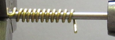 As you continue to rotate the chuck, vary the tension and angle on the wire to get as close as you can to the desired
coil spacing (you can adjust this later, but it's best to get as close as possible to start with).
As you continue to rotate the chuck, vary the tension and angle on the wire to get as close as you can to the desired
coil spacing (you can adjust this later, but it's best to get as close as possible to start with).
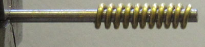
 Keeping the coil on the armature, you can stretch or compress the spring axially to get the coil spacing you need.
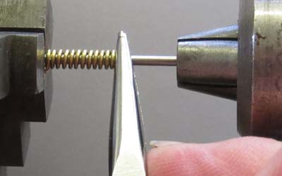
 You can also use a tool such as a screwdriver or knife blade to get the spacing. If you have enough hands, you can
do this as you wind the spring.
You can also use a tool such as a screwdriver or knife blade to get the spacing. If you have enough hands, you can
do this as you wind the spring.
 Slide back the tailstock and release the spring from the chuck.
 Trim off the waste at the ends of the spring.
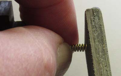 File the ends of the spring flat, using the free end of the armature to support it.
 Reset the armature in the chuck to the desired length of the spring.
 Cut the spring slightly overlength and file the cut end flat using the armature as a support and length gauge.
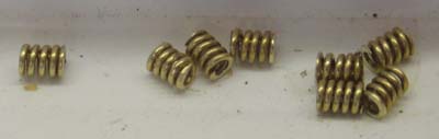 Little beauties. Results improve with practice - all very therapeutic!
Warranties
The procedures described in our instructions require the proprietary locomotive to be dismantled
and some
of its components to be modified. The manufacturer's warranty will almost certainly be rendered
void by carrying out the modifications. The user should ensure that the locomotive is free running and
has no warranty issues before commencing work.
Please follow the manufacturer's instructions for the dismantling
of the locomotive.
Our instructions guide you in making modifications to components of the locomotive and fitting the kit.
The modifications, the kit and
the instructions have been tested by the kit designer and others to confirm that they are practical,
serviceable and, when used as intended, produce a working locomotive whose performance will bring
much pleasure.
However, as the fitting of the kit by the user is out of our direct control, we can make no warranty,
expressed or implied, as to the performance and continued serviceability
of the locomotive following modification.