 Remove one of the bogies from the chassis block.
Following the manufacturers' recommendations for running-in, ensure that the locomotive is performing smoothly and to your satisfaction generally. Deal with any issues now, especially those covered by warranty or your basic statutory rights as customer, before making any modifications.
Separate the body moulding from the chassis block of the locomotive according to the manufacturer's instructions.
Gently slide four cocktail sticks between the body and chassis block, one to the side of each body retaining clip, just far enough to hold the clips clear of the chassis block so that the body may be slipped easily off the block.
Make a note of the identification of the sockets on the circuit board to which the two wire power feeds from each bogie are connected. Note also to which side of each bogie the wires go. Unplug the power feeds from the circuit board.
Remove one of the bogies from the chassis block.
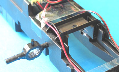
 To dismantle the Heljan bogie retaining assembly, unclip the top cover of the
drive unit as shown. This will allow the two halves of the unit to be separated slightly,
allowing the worm gear and bearings to move a little, which in turn allows the bottom of the
circular part of the 'yoke' to be unclipped from the drive unit.
To dismantle the Heljan bogie retaining assembly, unclip the top cover of the
drive unit as shown. This will allow the two halves of the unit to be separated slightly,
allowing the worm gear and bearings to move a little, which in turn allows the bottom of the
circular part of the 'yoke' to be unclipped from the drive unit.
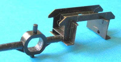
 Remove the plastic yoke.
Strong finger pressure, to lift the edge of the moulded ring over the edges of the chassis block, will allow the yoke to be slid sideways as shown, at which point one end of the moulding becomes free of the block. The moulding is then easily removed.
Assign the bogie to one or other of your sets of etched bogie parts, marking the bogie drive, drive shaft and chassis block accordingly.
Similarly remove the other bogie.
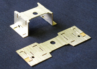 Remove one of the Pivot Frames (12) from the fret. Check that the slots running parallel with its long edges
are clear to take the material thickness and make the four folds as shown.
Remove one of the Pivot Frames (12) from the fret. Check that the slots running parallel with its long edges
are clear to take the material thickness and make the four folds as shown.
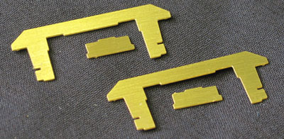 Remove two of the Pivot Flanges (11) and Ribs (13) from the fret.
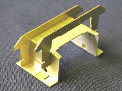 Slot the two Flanges into the Frame.
 Slot the two Ribs into the sides of the assembly.
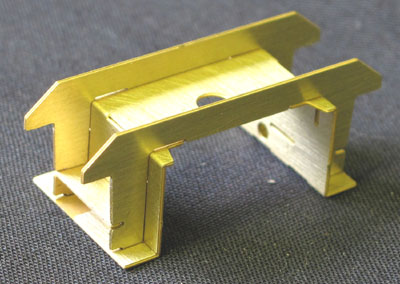
Solder up the pivot frame components. Test fit the nylon insulators through the pivot holes.
Repeat for the second pivot frame.
 Test fit the pivot frame assemblies in place in the chassis block, lined up with the holes which
retained the plastic yokes. Get them facing the right way: the new pivot location is further towards the outer
end of the loco than the original.
Test fit the pivot frame assemblies in place in the chassis block, lined up with the holes which
retained the plastic yokes. Get them facing the right way: the new pivot location is further towards the outer
end of the loco than the original.
You may need to clean up the casting a little to get them to sit down flush
at the base, with their outriggers resting on the top edge of the casting.
Secure the pivot frames in place. The frames may be secured by lengths of 3mm plastic rod inserted through the holes in the sides of the chassis casting and engaging in the square sockets in the sides of the frame assemblies.
 You may need to file flats on the lower faces of the rods to
get them to fit in the sockets. The plastic cylindrical shafts of the original yokes, cut off,
make suitable rods for this purpose if you are prepared to sacrifice them.
You may need to file flats on the lower faces of the rods to
get them to fit in the sockets. The plastic cylindrical shafts of the original yokes, cut off,
make suitable rods for this purpose if you are prepared to sacrifice them.
For added security you might wish to glue the base plates to the chassis on a bed of epoxy resin.